
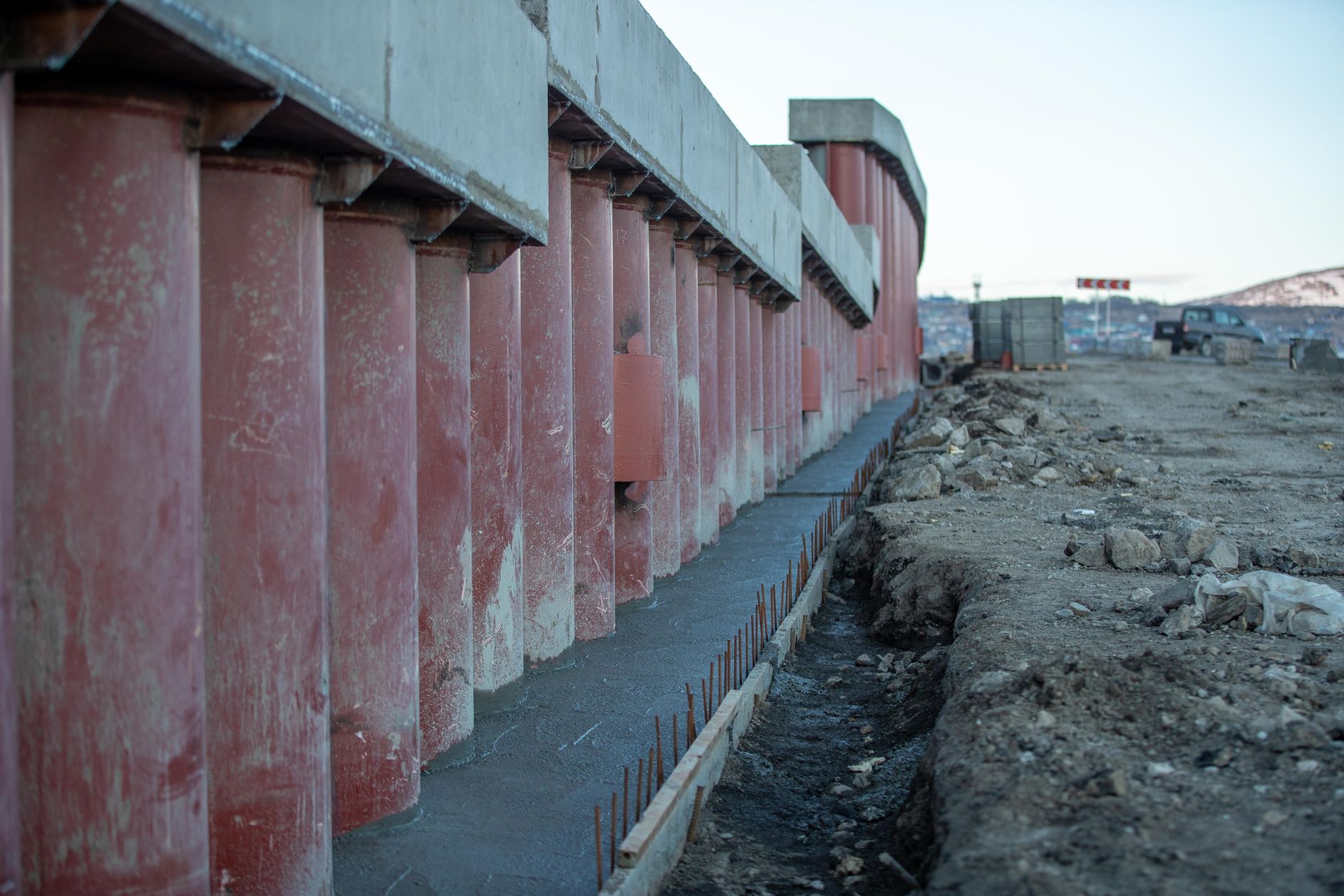
Traffic signal pole foundations sit out of sight below the kerb line, which is probably why they attract less design attention than the hardware above them. That's a mistake. A poorly designed or inadequately specified foundation leads to pole lean, cracking at the base plate, vibration fatigue, and in severe cases, structural failure. The engineering decisions made at foundation stage also affect cabinet placement, maintenance access, and the structural assumptions used when specifying signal head mounting configurations.
What determines foundation type and depth
Three factors dominate the foundation specification: soil bearing capacity, pole height and head configuration, and design wind speed for the site location. In Australia, wind loading is governed by AS/NZS 1170.2, and the design wind speed varies considerably between coastal and inland locations. A mast arm pole on a coastal corridor in Queensland faces a meaningfully different wind load envelope than a post-top installation on a low-speed urban street in Adelaide.
Soil bearing capacity must be measured, not assumed. Geotechnical investigations at or adjacent to the installation point give a foundation designer the data needed to size the drilled shaft or footing correctly. Relying on tabulated soil class defaults from a regional survey is a shortcut that frequently produces undersized foundations in areas with fill, made ground, or variable clay profiles.
Pole height matters because the overturning moment at the base scales with both height and head weight. A single post-top signal head on a 4.5-metre pole produces a fraction of the moment generated by a 10-metre mast arm carrying two or three signal heads plus a pedestrian signal assembly. That moment must be resisted by both the pole-to-foundation connection and the foundation-to-soil interface. Under-designing either one transfers the problem to the other.
Drilled shaft vs. direct embedment
The two most common foundation approaches for traffic signal poles in Australia are drilled concrete shafts (sometimes called bored piers) and direct embedment with backfill compaction. Each suits different site conditions.
Drilled concrete shafts are the standard choice for mast arm poles and any installation in soft or variable soils. The shaft diameter and depth are sized to resist both the overturning moment and any axial load from the pole and head assembly. Reinforcement cage design follows the structural load calculation. Where rock is encountered at shallow depth, a socket into the rock face provides excellent lateral resistance without needing significant shaft length.
Direct embedment suits lighter post-top installations in stable, competent soils with good bearing capacity. The pole base is set into the excavated hole and backfilled with compacted granular material or concrete depending on load requirements. It's a simpler construction sequence, but it offers less control over long-term performance in expansive or reactive soils.
In either case, the finished installation must achieve true vertical alignment within the tolerance specified by the relevant authority standard, typically within 1 degree of plumb. Corrections after the concrete has cured are expensive and structurally compromising.
Base plate and anchor bolt specification
Most modern traffic signal poles use a bolted base plate connection rather than direct embedment of the pole shaft. The anchor bolt group is cast into the concrete foundation during the pour, and the pole base plate bolts down onto a levelling nut arrangement that allows fine alignment adjustment before final tightening.
Anchor bolt specification is a structural design output, not a hardware selection. Bolt diameter, thread form, embedment depth, projection length, and steel grade all flow from the applied load calculations. Using a bolt group that's undersized for the actual pole and head configuration creates a fatigue failure mode that may not manifest for years, then fails suddenly under moderate wind loading.
Corrosion protection for anchor bolts in roadside environments deserves explicit specification. Hot-dip galvanising to AS 4680 is the standard approach. In marine or industrial corrosion zones, additional protection through bolt sleeve grease or stainless steel fasteners may be warranted. The nuts and washers must match the bolt protection class. Mixing galvanised bolts with unprotected mild steel hardware accelerates corrosion at the contact interfaces.
Drainage and water ingress at the base
Water pooling around the pole base is a consistent contributor to long-term corrosion damage. The grout bed between the base plate and the foundation surface must be detailed to shed water rather than trap it. A slight chamfer or drain gap in the grout profile keeps the base plate dry. Where traffic spray is likely, a sacrificial coating system applied to the lower section of the pole shaft provides additional protection.
Some authorities require a conduit stub-out or draw pit adjacent to the foundation to allow future cable additions or replacements without disrupting the base. This is worth including at construction stage. Retrofitting a conduit route past an existing foundation is disproportionately expensive. Good planning at this stage also supports better termination and splicing practice for the signal cabling that terminates at the pole base.
Common specification errors
Several errors appear repeatedly in traffic signal foundation specifications.
- Wind load underestimation: Selecting a wind speed from the wrong locality class under AS/NZS 1170.2, particularly in terrain transitions from open to suburban exposure categories.
- Soil data gap-filling: Using assumed bearing capacity values when site-specific geotechnical data is available but hasn't been reviewed by the foundation designer.
- Future-proofing omissions: Sizing the foundation for the initial head configuration without allowing for the additional heads or mast arm extensions that are often added during later upgrades.
- Tolerance on anchor bolt placement: Setting anchor bolts from an approximate survey mark rather than a surveyed set-out point, then finding the base plate won't align with the pole shaft.
None of these are obscure problems. They're documented consistently in defect reports from councils and road authorities across Australia, and they're almost always cheaper to address at design stage than after installation.
Coordination with underground services
Signal pole foundations sit in busy service corridors. Water mains, gas, power, communications conduits, and stormwater drainage all compete for the same subgrade space near intersections. A foundation drilled into an unlocated service causes delays, cost, and potentially serious safety incidents.
Dial Before You Dig requests and potholing of critical service alignments should be treated as mandatory pre-construction steps, not optional risk items. The foundation designer needs confirmed service clearances before finalising shaft location and depth. Where conflicts exist, the foundation geometry may need to change, and that change should flow through to the structural calculation, not be absorbed in the field without recalculation.
Bob Panich Traffic Signals specifies and delivers traffic signal infrastructure with attention to foundation design as a structural and operational engineering requirement, not a construction afterthought. The signal controller hardware installed above ground is only as reliable as the structure it's mounted on. Getting the foundation right at the start avoids the more costly process of correcting it later.