
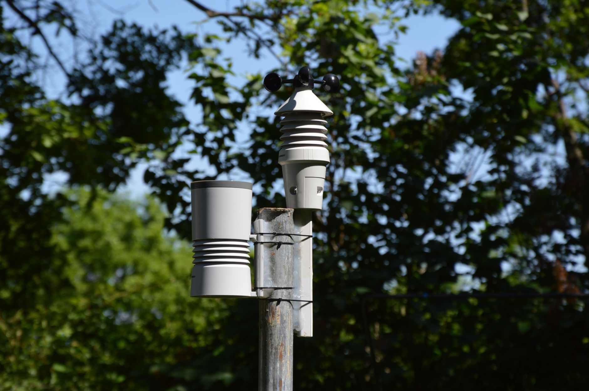
Smart city sensor placement is rarely treated as a discipline in its own right. Procurement teams specify sensors. Civil engineers mount them. Software teams ingest the data. Nobody owns the question of whether the device is actually in the right position to observe the right thing. That gap produces poor data quality, redundant infrastructure, and coverage blind spots that cost far more to fix post-installation than they would have during design.
Bob Panich Traffic Signals works across signalised intersections and intelligent transport infrastructure where sensor positioning directly affects signal timing decisions, pedestrian safety logic, and network-wide coordination. The placement principles that apply at an intersection extend to every IoT node in a smart city deployment.
Why position determines data quality
A sensor's physical location controls three things simultaneously: what it can observe, what interferes with that observation, and how reliably it communicates the result. Change any one of these and the data changes with it.
Consider a pedestrian counting sensor mounted on a column that gets partially shaded by a mature street tree for six hours each day. Optical sensors lose accuracy in dappled light. A radar sensor on the same column avoids that problem entirely but may pick up vehicle spillover if the lane is within its detection cone. Neither failure is obvious until the data is validated against manual counts weeks later. The fix requires a cherry picker, a new bracket, and a re-configuration of the zone masks.
The same logic applies to road-surface sensors, environmental monitors, and connected vehicle roadside units. Mounting height, azimuth angle, nearby reflective surfaces, and proximity to interference sources all interact. A site survey that takes two hours before installation is worth far more than a data audit that takes two months after it. On projects that integrate IoT sensor networks for live urban traffic data, placement errors compound across every downstream system that depends on accurate inputs.
The three placement variables that matter most
Most placement failures trace back to underweighting one of three variables: field of view, mounting height, and communication path. They're interdependent, so optimising one in isolation often degrades another.
Field of view sets the detection geometry. For intersection sensors, the standard is to position the device so its detection zone covers the full approach lane without extending into the adjacent lane. That sounds straightforward but gets complicated quickly at skewed intersections, where approach angles shift the detection footprint by as much as 30 degrees. Radar-based detectors tolerate oblique angles better than inductive loops, but they require careful zone masking to avoid counting vehicles in the turning pocket as through-traffic.
Mounting height governs both detection accuracy and maintenance access. Too low and a sensor in a pedestrian zone gets occluded by parked bicycles, temporary barriers, and standing crowds. Too high and the depression angle narrows the detection field to a strip that misses queue tails. For most urban intersection sensors, a mounting height of 4.5 to 6 metres gives the best balance of coverage and occlusion resistance. That range also keeps the device within reach of a standard elevated work platform without requiring a full traffic management closure.
Communication path is the most frequently ignored variable at the placement stage. A sensor generating reliable data is worthless if its wireless link to the field controller is blocked by a concrete bus shelter, a new building facade, or a recently upgraded transformer vault. Point-to-point 5.8 GHz links that were line-of-sight at installation can lose 12 to 15 dB of margin within two years as urban streetscape changes. Mesh architectures help, but they don't eliminate the need to verify that at least one reliable path exists from each node at commissioning.
Intersection placement versus corridor placement
Intersection and corridor deployments impose different placement constraints.
At an intersection, sensor positions are largely fixed by the signal head locations, the stop line geometry, and the detection zone requirements of the signal controller. The goal is complete coverage of each approach with minimal false calls. Placement decisions here are well-covered by AS 2220 and the relevant transport authority specifications.
Corridor deployments are less constrained and therefore less disciplined. When a transport authority deploys sensors along a 3-kilometre arterial to measure travel times, spacing and position are both design choices. Spacing too widely and you lose the ability to localise incidents. Spacing too closely and you multiply costs without adding resolution. The right spacing depends on the road geometry, the speed profile, and what the data feeds into: a variable message sign system needs coarser resolution than an adaptive signal control network. Adaptive signal control systems, for instance, require sensor inputs that accurately reflect queue length and saturation at each approach, making placement precision critical to the timing algorithm's ability to respond.
Environmental factors that change over time
Placement decisions assume a static environment. Urban environments aren't static.
Street trees grow. New buildings cast new shadows. Temporary construction hoardings become permanent facades. A bus stop that didn't exist at the time of the site survey gets installed six months after commissioning. Each change can degrade sensor performance without triggering any obvious fault condition. The controller still receives data. The data is just wrong in ways that standard alarms don't detect.
This is why the most resilient sensor placement strategies include a documented site baseline: photographs, measured field of view, signal strength readings, and detection zone masks captured at commissioning. When performance degrades, the baseline is what confirms whether the sensor has drifted or the environment has changed around it. Without it, fault-finding is guesswork.
Thermal cycling also affects physical mounts over time. Roadside cabinets and pole-mounted hardware experience bracket fatigue from repeated heating and cooling cycles. A sensor that was precisely aligned at installation can shift by several degrees over two to three years on a steel pole with a high daily temperature range. Stainless fasteners and locking compounds resist this better than standard galvanised hardware.
Coordinating placement with data governance
Sensor placement has a governance dimension that's easy to overlook during engineering design. Every mounted sensor collects data. That data has an owner, a retention requirement, and potentially a privacy implication if it captures images or unique identifiers.
Mounting a camera-based pedestrian counting sensor facing a café forecourt requires a different privacy analysis than mounting the same sensor facing a lane approach. The physical position determines the data scope, and the data scope determines the governance obligations. Smart city programmes that get placement right from the start reduce the compliance remediation work that follows when privacy officers review the deployment post-installation.
This connection between physical infrastructure and data policy is a defining feature of smart city governance. As Australian cities navigate questions of who owns the data collected at the kerb, the placement decisions made by transport engineers and infrastructure contractors become directly relevant to broader data governance frameworks.
Practical steps for placement planning
A placement planning process doesn't need to be elaborate. It needs to be deliberate. Bob Panich Traffic Signals applies the following steps on ITS and signal projects where sensor placement is a design element:
- Conduct a physical site survey at the time of day when lighting and traffic conditions are most demanding for the sensor type being used.
- Document existing and known future obstructions within the detection zone and communication path.
- Confirm mounting height against maintenance access requirements, not just detection geometry.
- Test wireless link margin at commissioning using actual hardware, not modelled estimates.
- Capture a baseline dataset during commissioning for each sensor node, including zone masks and signal strength readings.
These steps don't eliminate all placement risk. They do shift the point of failure from the field, where corrections are expensive, to the design stage, where they're cheap. Sensor networks that are placed well from the start require less remediation, generate cleaner data, and integrate more reliably with the adaptive and automated systems that depend on them.