
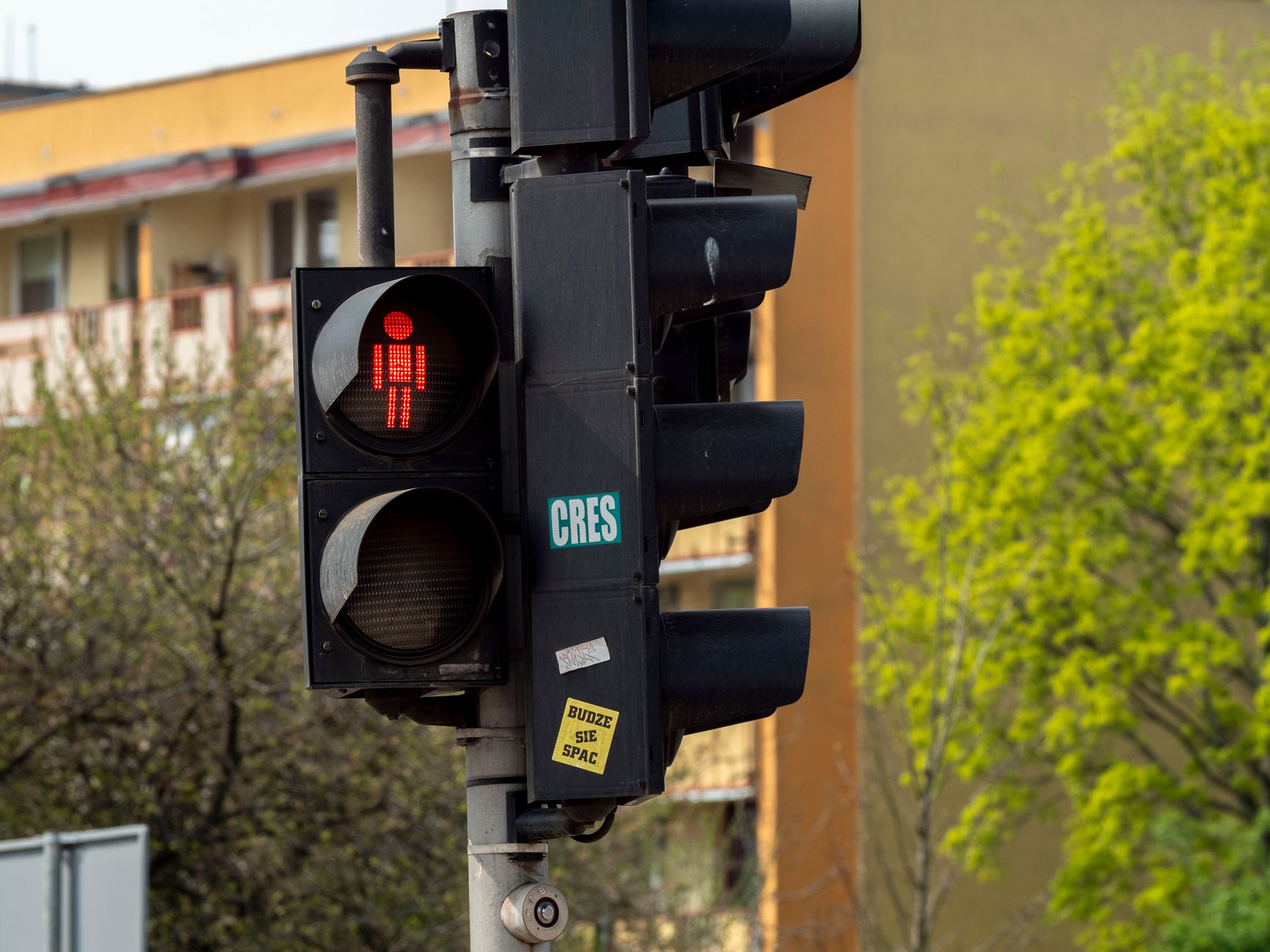
Wrong-way driver detection sits at an uncomfortable edge of traffic signal engineering. The events are infrequent enough that many practitioners treat detection as a future concern, yet serious enough that a single incident on a divided arterial or freeway ramp can kill multiple road users within seconds of the wrong turn being made. Standard vehicle detection technology at signalised intersections is designed to confirm presence and queue depth in the correct travel direction. It wasn't built to flag a vehicle moving against the intended flow, and on most installations, it won't.
The gap matters more now than it did a decade ago. Australian road agencies have adopted smart intersection design frameworks that push more sensing capability to the kerb, and the same infrastructure that supports adaptive signal control can, with the right configuration, support contraflow detection. The engineering challenge is not exotic. It's a question of sensor orientation, logic thresholds, and response protocols.
Why standard detection misses contraflow vehicles
Inductive detector loops embedded in pavement measure the change in inductance caused by a metal vehicle passing over the coil. A loop placed at the stop line to count approaching vehicles will register a signature whether the vehicle is travelling in the correct direction or not. It detects presence, not direction. A wrong-way driver crossing the loop still looks like a detection event. The controller sees a vehicle where it expects one, and nothing triggers an alert.
Video-based detection systems have the same blind spot when configured only for presence or density. A standard video detection zone set up to count vehicles in an approach lane will count a vehicle entering from the exit if the zone boundary overlaps. The system doesn't know it's looking at a contraflow movement unless the software has been specifically configured to assess direction of travel within the zone.
This is why wrong-way detection requires purpose-built logic, not just additional sensors. The sensing layer matters less than the analytical layer sitting above it.
Detection methods that can identify contraflow movement
Three sensing technologies are currently used in deployed wrong-way detection systems, each with different strengths depending on the installation context.
Directional radar. Doppler radar units mounted on signal poles or overhead gantries can resolve both speed and direction of travel. A vehicle moving toward the radar source on an outbound lane registers as a positive Doppler shift rather than the negative shift expected for that travel direction. Radar units used for this purpose need a clear sightline down the departure lane or ramp and should be mounted to minimise cross-traffic interference. Response time is fast, typically under two seconds from wrong-way entry to alert generation.
Directional video analytics. Modern video processors running on-device or at a roadside edge compute unit can assign a direction vector to each tracked vehicle. A vehicle tracked moving from stop line toward the intersection on a one-way outbound approach generates a direction vector that contradicts the expected flow axis. Alert thresholds are usually set to require a minimum speed and a minimum travel distance in the wrong direction before an alarm fires, filtering out slow pedestrian crossings or service vehicles reversing short distances. Bob Panich Traffic Signals integrates this type of analytics layer into smart intersection deployments where the camera infrastructure already exists for queue and saturation flow monitoring.
Paired loop signatures. Two closely spaced detector loops, oriented perpendicular to the lane axis and wired into a controller that can time the sequence of actuation, can resolve direction of travel. A vehicle approaching correctly actuates loop A before loop B. A contraflow vehicle actuates B before A. The timing difference is small, typically 50–150 milliseconds at urban speeds, which means the controller firmware needs to be able to log and compare loop actuation timestamps at millisecond resolution. Not all legacy controllers support this natively, but it's a cost-effective retrofit option on installations where loop infrastructure already exists and a firmware update is feasible.
Where to prioritise installation
Wrong-way events concentrate at specific geometry types. Freeway on-ramps and off-ramps account for the majority of reported incidents in Australian crash data, followed by divided arterials with separated left and right-turn slip lanes, and one-way urban streets adjacent to car parks or service lanes. Signalised intersections at the base of freeway ramps are the highest-priority locations because they combine the geometry most likely to confuse a disoriented or impaired driver with a high-speed environment where recovery time is essentially zero.
Urban intersections with contraflow bus lanes or bicycle lanes present a secondary risk profile. A vehicle entering a contraflow bus lane will be travelling toward oncoming buses at combined closing speeds that leave no time for either driver to react. Bicycle detection at signalised intersections already addresses part of this problem by identifying cyclists in dedicated lanes, but wrong-way motor vehicle detection in those same lanes is a separate requirement with different sensor configurations.
Response integration: what happens after detection
Detection without response is an incomplete system. The detection event needs to trigger a response chain that actually reduces crash probability in the 10–30 seconds available after a wrong-way entry is confirmed. Response options used in current deployments include:
- Activating variable message signs (VMS) downstream of the wrong-way vehicle to warn oncoming drivers.
- Triggering a red phase on all signal groups at the intersection to halt cross-traffic until the vehicle is no longer in the zone.
- Sending an automated alert to the traffic management centre and, where protocols permit, to the relevant road authority's incident response team.
- Activating roadside LED wrong-way warning signs mounted on the departure ramp or lane.
The signal controller response is the fastest element of the chain. An automated phase termination triggered by a confirmed wrong-way event can halt conflicting movements within one signal cycle, often within 3–5 seconds of the detection threshold being crossed. This is substantially faster than an operator-initiated response from a traffic management centre, even one monitoring live video feeds.
Integrating wrong-way response logic into the signal controller requires coordination with the traffic authority's signal timing plans and fail-safe design requirements. Any automated override of normal signal sequencing must go through the same conflict monitoring checks as standard phase transitions. It can't bypass the safety interlocking that prevents simultaneous conflicting green phases.
Data and logging requirements
Wrong-way detection events need to be logged with precision for post-incident analysis, insurance purposes, and system calibration. The minimum log record should include a timestamp to millisecond resolution, the detection method that triggered the event, the lane or approach identifier, the duration of the contraflow movement, and the system response actions taken. Video clips should be captured automatically on event trigger and retained for a minimum period aligned with the road authority's data retention policy.
This logging requirement connects directly to the broader data management discipline in smart intersection infrastructure. Data logging in traffic signal cabinets covers how operational event data is structured and stored at the controller level, and the same principles apply to wrong-way detection records: write frequency, storage medium durability, and retrieval speed all affect whether the data is actually usable when it's needed.
False positive management
False positives are the practical failure mode that gets wrong-way detection systems disabled or ignored in the field. Emergency vehicles, maintenance trucks, and pavement marking crews all operate in ways that can trigger a naive contraflow detection rule. A sweeper travelling slowly along a departure lane in the early hours will generate the same directional signature as a wrong-way driver at low speed.
Filtering strategies include minimum speed thresholds (typically above 15 km/h for a confirmed alert), time-of-day suppression windows for scheduled maintenance, and a two-sensor confirmation requirement before any automated response is activated. Austroads guidance on road safety infrastructure design provides a framework for setting alert thresholds that balance detection sensitivity against false positive rate, and that guidance should inform the configuration parameters on any new installation.
Radar-based systems generally produce fewer false positives than loop-pair systems in high-traffic environments because the Doppler signature resolves speed and direction simultaneously. Video analytics systems produce fewer false positives than either when the analytics engine is tuned for the specific geometry of the installation, but they require more commissioning time and are more sensitive to camera positioning and lighting changes.
Integration with smart intersection platforms
Wrong-way detection is most effective when it's integrated into the same intersection management platform that handles adaptive signal control and queue detection, rather than deployed as a standalone system with a separate communication path. Integration means the wrong-way detection logic has direct access to the current signal state, which in turn allows the response logic to make context-aware decisions: a red phase imposed during an already-red period has no safety value, while the same phase imposed during a conflicting green period may prevent a collision.
Bob Panich Traffic Signals designs and supplies intersection infrastructure for Australian road authorities, incorporating detection, control, and response integration as a single engineered system. Contraflow detection capability is specified from the design stage, not retrofitted after commissioning, which ensures the sensor placement, controller firmware, and data management architecture are all aligned from the outset.