
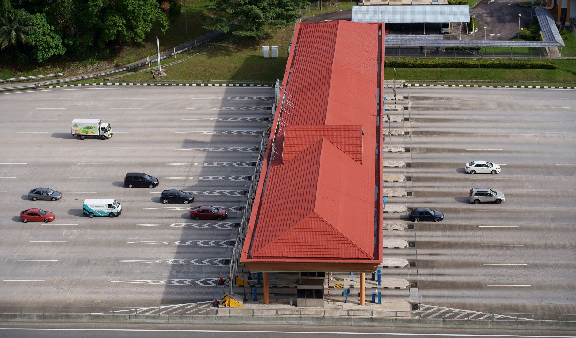
Contraflow signal design sits at the intersection of operational flexibility and safety-critical engineering. Reversible lanes are a well-established tool for stretching road capacity without adding physical infrastructure: a lane that serves inbound traffic during the morning peak runs outbound during the afternoon peak. The problem is that the signal systems governing those transitions carry failure modes that standard intersection design simply doesn't encounter. Getting the logic right matters a great deal.
What makes reversible lanes different
A fixed lane has one permitted direction. The signal controller serves that direction consistently, and conflict monitoring checks against a known set of opposing movements. A reversible lane changes its permitted direction on a schedule or on operator command, which means the controller must handle a transition state where neither direction is confirmed safe until the previous one has fully cleared.
That transition window is the core engineering challenge. During it, vehicles may still occupy the lane from the outgoing direction while the system prepares to admit traffic from the opposite end. Standard intergreen periods, which are calculated for a fixed conflict geometry, don't cover this scenario. The clearance interval for a reversible lane must account for the full length of the lane, not just the width of an intersection.
In practice, this means contraflow signal designs require an all-red or all-stop interval that scales with the lane's length and the prevailing speed limit. A 500-metre reversible lane on a 60 km/h arterial needs a longer clearance buffer than a 200-metre segment on a 50 km/h road. Many early contraflow installations underestimated this interval, producing arrangements where a slow-moving vehicle at the far end of the lane could legally still occupy it when opposing traffic received a green.
Phase interlocking and interlock verification
The signal phases governing a reversible lane can't operate independently. Each must be interlocked so that a green for one direction physically prevents a green for the opposing direction from being displayed. This sounds obvious, but the implementation detail matters. Software-only interlocks can fail under fault conditions, and a software fault that clears an interlock is precisely the scenario where the physical consequences are most severe.
Best practice in Australian contraflow installations uses both software interlocks and hardware relay logic that operates independently of the controller's main processor. If the processor hangs or enters an indeterminate state, the relay logic holds the opposing signal in red-and-yellow or flashing amber until a valid interlock confirmation is received. This is a direct application of fail-safe design principles: the safe state is always no movement rather than continued movement on stale data.
Verification of interlock status before each direction change is equally important. The controller should confirm that the current active direction's signal has gone to red, that a timer confirming the clearance interval has elapsed, and that any lane-occupancy sensors in the reversible segment are reporting clear before issuing the interlock release. Skipping any of these steps to reduce transition time is a false economy.
This kind of turn-phase logic, including the sequencing of competing movements through defined interlocking rules, is closely related to broader turn-phase sequencing in signal controllers, where ordering competing movements incorrectly carries similar safety consequences.
Detection requirements along the lane
A reversible lane needs detection that covers its entire length, not just the stop line. A standard inductive loop at the intersection entry tells the controller whether a vehicle is waiting. It says nothing about whether the lane itself is clear during a direction transition.
Modern contraflow installations use a combination of detection technologies. Inductive loops at fixed intervals provide reliable occupancy confirmation in defined zones. Video analytics overlaid on the lane can flag stationary or slow-moving vehicles between loop positions. Some deployments add radar-based presence detection at mid-lane points, particularly where the lane length exceeds 300 metres.
The detection data feeds directly into the clearance interval logic. If any mid-lane sensor reports occupancy during the transition period, the controller holds the all-stop state and alerts the traffic management centre rather than proceeding to the new direction. This automatic hold is not optional in a compliant system. An operator override that bypasses occupancy confirmation during a live transition is a configuration that should not exist.
These detection strategies share a conceptual foundation with spillback detection systems, which similarly require controllers to see conditions beyond the immediate stop line before making phase decisions.
Overhead lane control signals
The signal heads that communicate reversible lane status to drivers are a separate consideration from the intersection signals. Overhead lane control signals, typically mounted on gantries above each lane, display a red cross (lane closed), a green arrow (lane open in that direction), or a flashing amber X (transitioning or cautionary).
These signs must be fail-safe in their own right. A sign that loses power should default to the red cross, not to an off state that a driver might interpret as lane-open. The power supply circuit for the overhead signs should be monitored continuously, with any supply fault triggering both a maintenance alert and a reversion to the safe closed display.
Visibility standards for overhead lane control signals are more demanding than for standard signal heads because drivers are reading them at speed from greater distances. AS 1742.13 sets out the requirements in Australia, and compliance checking during commissioning should include photometric verification at the design approach distances, not just a visual pass-fail inspection from the footpath.
Timing coordination with adjacent intersections
A reversible lane rarely exists in isolation. It typically connects two or more signalised intersections, and the direction change must be coordinated across all of them simultaneously. If the upstream intersection switches to admit inbound traffic before the downstream intersection has confirmed the lane is clear and its own signals have transitioned, the result is opposing vehicles entering the lane from both ends.
Coordination is handled through a centralised controller or traffic management system that issues a simultaneous command to all intersections on the reversible segment. Each intersection controller acknowledges the command and confirms its local interlock status before the segment-level direction change is logged as complete. The command-acknowledge-confirm cycle adds a few seconds to each transition but is non-negotiable for safety.
Where communication latency between intersections is a concern, the segment-level controller uses a conservative timeout. If all acknowledgements aren't received within a defined window, the transition is aborted and all intersections hold the previous direction until the fault is diagnosed. This is particularly relevant on older communication infrastructure where packet loss or latency spikes are possible.
Operational considerations and maintenance access
Contraflow systems require maintenance procedures that account for the lane's operating status. Technicians entering the lane for loop maintenance or sign inspection must have a formal process for taking the lane out of service and locking it in the red-cross state before entry. A maintenance mode that can be set at the traffic management centre, confirmed locally at the cabinet, and logged with a timestamp is the baseline requirement.
Cabinet placement is also worth attention during design. Controllers governing reversible lane signals should be accessible from the roadside without requiring the technician to cross the reversible lane itself. On narrow urban corridors this sometimes drives a decision to locate the primary cabinet on the median, which introduces its own access and security considerations. Getting this resolved at design stage avoids expensive retrofits later.
The documentation requirements for contraflow signal systems are more extensive than for standard installations. Phase diagrams, interlock logic schematics, lane clearance interval calculations, and the communications architecture connecting each intersection controller all need to be captured as part of the as-built record. These documents become essential when the system is modified or when a fault needs to be traced under time pressure.
Bob Panich Traffic Signals designs and delivers signal systems for reversible lane and contraflow applications across Australia, covering the full scope from phase logic design and interlock specification through to commissioning and documentation.